TikZ Package
TikZ is a powerful package for creating graphics and diagrams in LaTeX documents. With TikZ, you can create a wide variety of diagrams, such as flowcharts, mind maps, timelines, Venn diagrams, and much more. TikZ provides a lot of flexibility in terms of customization, so you can create graphics that match the style and formatting of your document. We can start by using the tikz package.
\usepackage{tikz}
In this course TikZ will help us construct State Diagrams in LaTeX documents. Use a few libraries that are part of the tikz package.
\usetikzlibrary{automata, arrows, positioning}
To start drawing the diagram, enclose the code within a tikzpicture block
\begin{tikzpicture}
…code for states and transitions…
\end{tikzpicture}
Before defining states and transitions, certain parameter values can be set using \tikzset. There are a lot of values that can be set but here are a few basic ones we use:
\tikzset{every state/.append style={thick,fill=white}}
\tikzset{every edge/.append style={-latex,thick}}
\tikzset{every loop/.append style={-latex,thick}}
Defiining a State/Node
Defining the Initial node:
\node[state,initial] (s) {start};
- The keyword “initial” is used to represent the state as initial state.
- (s) represents the id of the node. You can later reference the node by using the id “s”.
- {start} represents the name of the node as it appears on the diagram.
Defining normal nodes
\node[state] (a) [right of=s] {State a};\
\node[state] (b) [right of=a] {State b};
\node[state] (c) [below of=sb] {State c};
\node[state] (d) [below of=ab] {Satet d};
- [right of s] defines the alignment of state with id “a” with respect to state with id “s”. In the first line, “State a” will be the node to the right of the “start” state. Similarly we can use the keywords “left of” and “above of” also.
Defining Accepting nodes
\node[state, accepting] (e) [below of=bb] {State e};
- The keyword “accepting” is used to represent the state as an accepting state.
Defining State Transitions
Use the \path to start a set of transition functions
\path[->]
Define an edge using the following form:
(s) edge[loop above] node{0} (s)
- This is a self loop with that will be drawn above the node “s” when the input is 0. Note that the start and destination nodes of the edge are same. (s) edge[above] node{1} (a)
- Since there is no keyword “loop”, this means that is a normal edge that travels from node “s” to node “a” for an input of 1
- “above” indicates that the input value of 1 will be drawn above the edge. You can use “below”, “right” and “left” (a) edge[bend left, above] node {0} (b)
- “bend left” makes the edge bend to the left. This is useful when you have two edges between two nodes. You can also use “bend right”
- The edge always bends with respect to its direction.
It is very important to have a semi-colon at the end of your last edge. This is how \path knows your list of edges has ended.
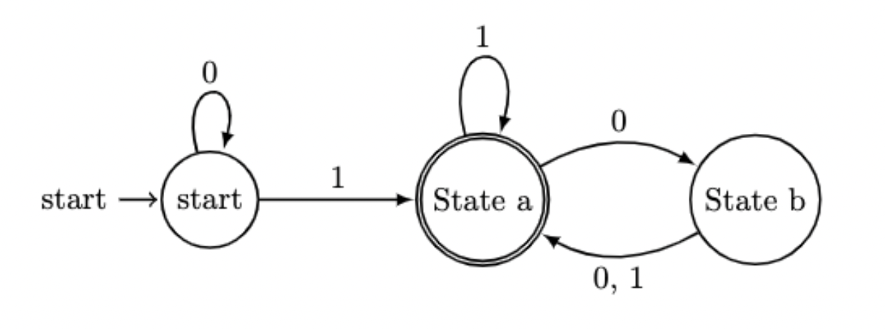
Sample Code:
\documentclass[10pt]{article}
\usepackage{tikz}
\usetikzlibrary{arrows,positioning, automata}
\begin{document}
\begin{tikzpicture}
\tikzset{every state/.append style={thick,fill=white}}
\tikzset{every edge/.append style={-latex,thick}}
\tikzset{every loop/.append style={-latex,thick}}
\node[state,initial] (s) {start};
\node[state, accepting] (a) [right of=s] {State a};
\node[state] (b) [right of=a] {State b};
\path[->]
(s) edge[loop above] node{0} (s)
(s) edge[above] node{1} (a)
(a) edge[loop above] node{1} (a)
(a) edge[bend left, above] node {0} (b)
(b) edge[bend left, below] node {0, 1} (a);
\end{tikzpicture}
\end{document}
The Diagram for this code: