Universal Turing Machine
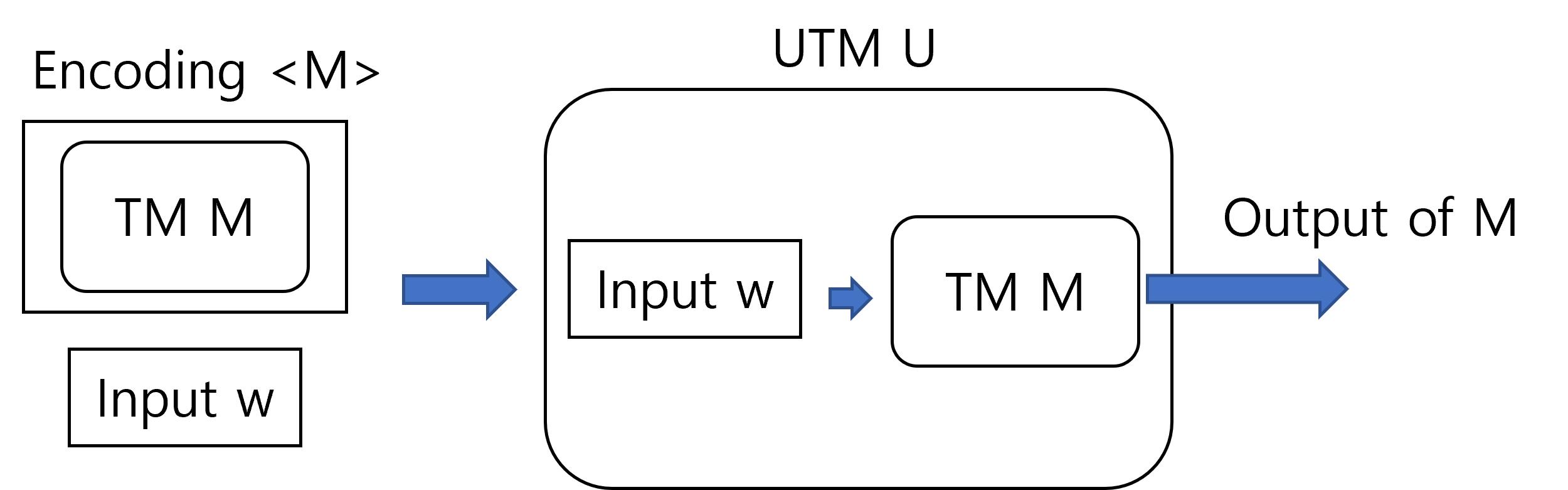
A universal turing machine(UTM) is a turing machine that can simulate any turing machines. That is, given an encoding $\langle M\rangle$ of a turing machine $M$ and an input string $w$ as the input, a UTM $U$ generates the output of running $M$ on the input $w$.
Encoding of a Turing Machine
Since UTM is a specific kind of TM, it takes strings as the input. Therefore, to feed a TM $M$ to a UTM $U$ as the input, $M$ must first be translated into strings. The translated string of $M$, or equivalently the string representation of $M$, is called an encoding of $M$, and is denoted as $\langle M \rangle$ in this course. If it doesn’t click, think of the relationship between a computer program and its code. A computer program is a sequence of operations that must be performed by the computer to achieve a certain task. However, we can’t directly deliver the sequence to the computer, so instead we write code that represents the sequence of operations and feed it to the computer. In our context, TM $M$ corresponds to a specific computer program, and the encoding $\langle M \rangle$ corresponds to the code of the program. As you may have noticed, the encoding method isn’t unique, so there can be multiple different encodings for a single TM. However, in most cases, we do not put much attention on the specific encoding method we consider, since regardless of the encoding scheme, the encodings are describing the same entity, which is the TM that we encoded. Therefore, we simply assume that the TM is somehow encoded properly and was provided as the input, also that we somehow can decode it properly to obtain the specification of the TM.
An Example of Encoding Scheme
A TM is defined as a 7-tuple $(Q, \Sigma, \Gamma, \delta, q_0, q_{a}, q_{r})$, and an encoding of a TM must contain information about all 7 elements in the tuple. However, the encoding does not necessarily have to explicitly describe the 7 elements, since a full description of the transition implicitly provides information of other elements as well. Suppose we are given a complete list of all possible transitions. Since the transition function is defined as $\delta:Q \times \Gamma \rightarrow Q \times \Gamma \times \{ L,R,S \} $, a single entry in the list would specify the current state, the tape symbol at the head, the new state after transition, the new tape symbol to be written at the head, and the direction to which the head must move. Therefore, we can extract all states of the TM that can be reached, all symbols that can be observed from the tape, and all symbols that can be written on the tape from the list of transitions. The remaining elements are the initial state $q_0$, the accepting state $q_a$ and the rejecting state $q_r$. We can bypass specifying the three elements by always letting the first, the second and the third states be the initial, the accepting, and the rejecting states respectively. In conclusion, a complete list of the transitions is considered as an encoding of a TM, given that we somehow implicitly specify the initial, the accepting, and the rejecting states.
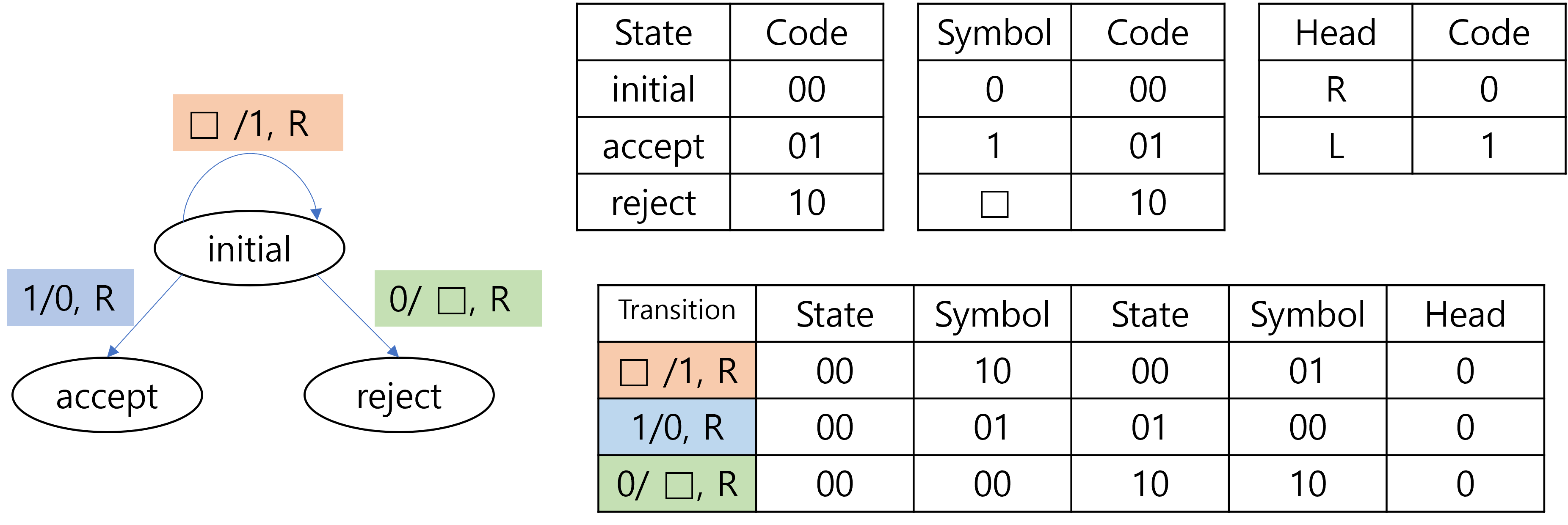
The remaining problem is how to represent the complete list of transitions as a string. To achieve this, observe that we have finite number of states, symbols and head directions. We can assign a fixed length sequence of bits to each state, symbol and head direction, and then simply concatenate them together to represent a single entry of transition. Below is a trivial example of the encoding scheme.
Encoding of a configuration
To simulate a TM, we need to keep track of the configuration of the TM. In other words, we need to memorize the current state, the tape content, and the head location of the TM during the simulation, in addition to the transition rules. Therefore, we also encode the configuration of the TM as a string and keep it in the tape of the UTM to simulate the TM. Again, there can be multiple ways to encode the configuration of the TM. The following figure describes one way of encoding the configuration.
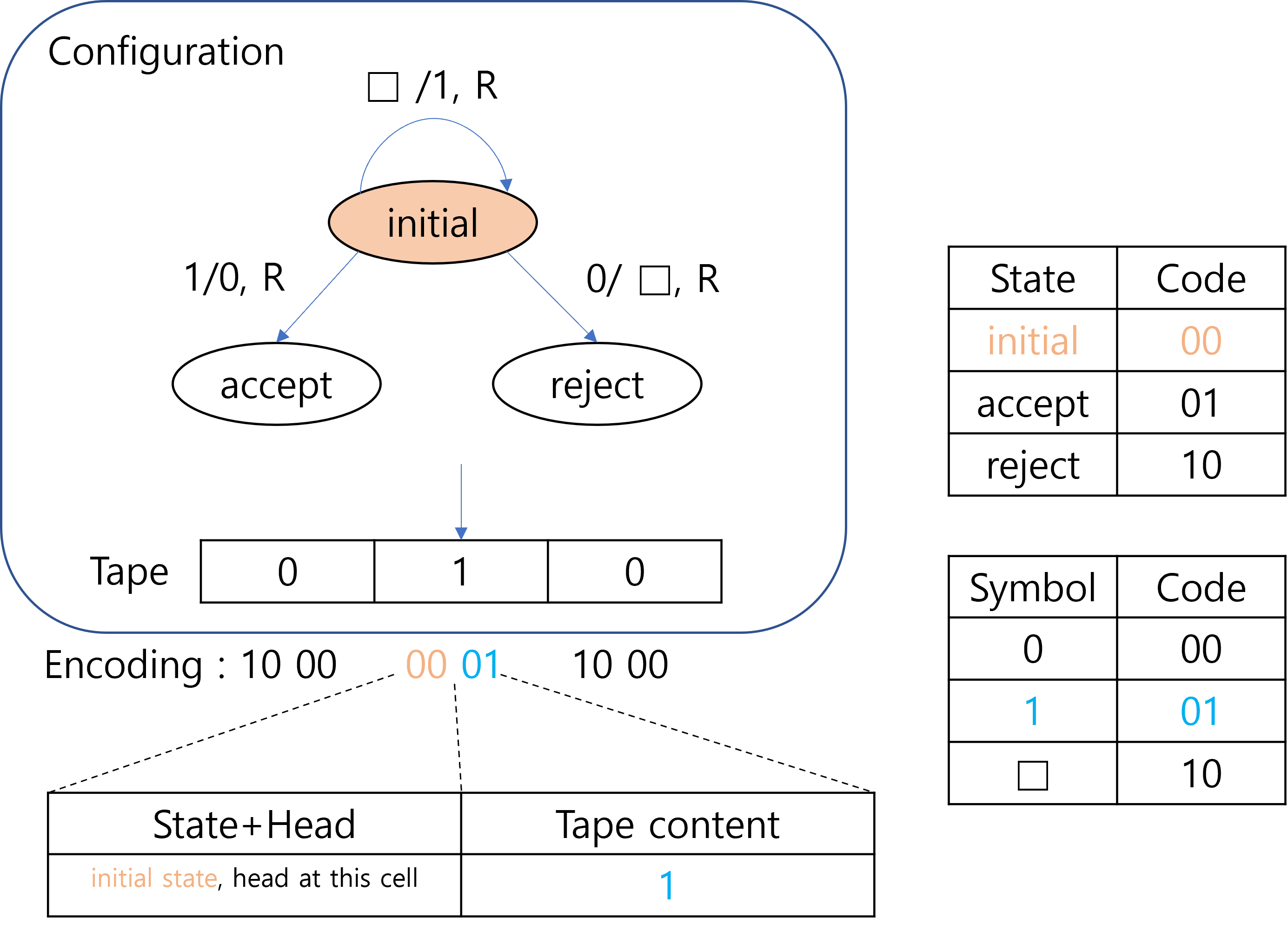
In the figure, every 4 bits block represent a single tape cell of the TM. Therefore the whole encoding in the example represents 3 cells of the tape. The first 2 bits of the 4 bits block represents the current cell as well as the current location of the head. Specifically, if the head is at the cell corresponding to the block, then the first 2 bits would be the code for the current state. Otherwise, the first 2 bits would be the code for the reject state. Since the first 2 bits of the second block is 00 which corresponds to the initial state, the encoding indicates that the current state is initial state, an also that the head is located at the second cell. The last 2 bits of the block represents the symbol stored in the cell. Currently, the three cells contains 010.
Simulation of a Turing Machine
So far, we saw how the specification and the configuration of a TM could be encoded. To actually simulate the TM, there are more details that should be explained, such as simulating the infinite blanks of the tape. However, we will not go over all the details in this post. Instead, we would briefly discuss how a TM can be simulated at a high level.
As described earlier, the UTM would be given an encoded specification(which is essentially the list of transitions) of a TM and the input string for the TM. Based on the input, we first initialize the configuration on the tape. This would contain information of the input string as well as the current state and the head location. Then, to simulate a single step of the TM, we
- Scan the current configuration to figure out the current state and the tape symbol.
- Scan the specification to figure out the transition corresponding to the current state and the tape symbol.
- Update the current state, tape symbol and the head location according to the transition.
If the TM eventually reaches an accepting state, then the UTM would return ACCEPT. If the TM reaches a rejecting state, then the UTM would return REJECT. This way we can update the configuration and return the out of the TM according to the specification of the TM, which shows that we can simulate the behavior of the TM on the UTM.
Additional Resources
- Textbooks
- Erickson, Jeff. Algorithms
- Sipser, Michael. Introduction to the Theory of Computation
- Chapter 3 - Turing Machines
- Sariel’s Lecture 8.6
